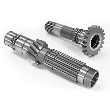
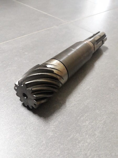
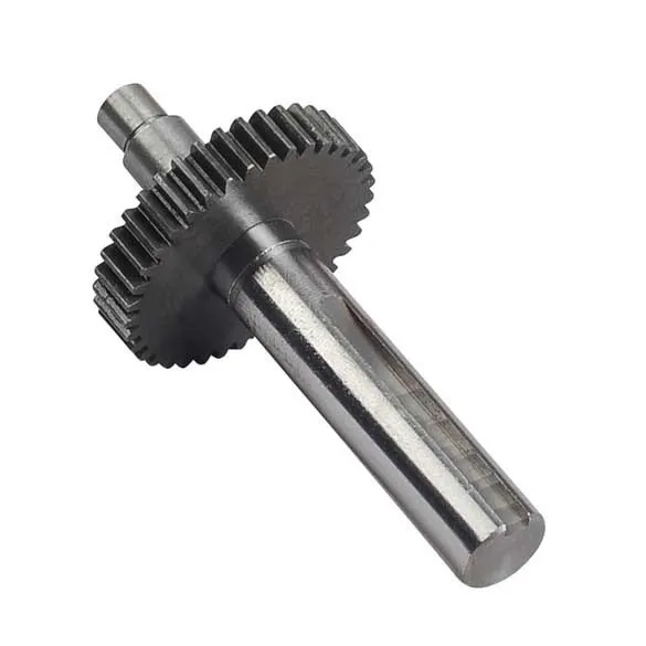
Product Description
Our Advantage
1.Quick response within 12 hours
2.Accept small order(MOQ:1pcs)
3.Custom service.Unusual packaging,standard packing or as customer required
4.Excellent after-sales service
5.Strict quality control system.100% factory testing and inspection personnel in accordance with international standards for the high-frequency sampling, to ensure the quality of products manufacture d
6.Accept ODM&OEM
| Reducer Model | Applicable Machine Model | Motor Install Hole | Housing Install Hole | Shaft Pinion Gear Diameter | Shaft Pinion Gear Height | Shaft Pinion No. Teeth | Weight/kg | ||
| A | B | C | H | Z | |||||
| GS11A05 | SDLG6205-6210Rotary | φ282 | 8-M14 | φ360 | 11-φ22 | φ194 | 91 | 25 | 144.47 |
| GS11A06 | Hyundai215vs Rotary | φ224 | 4-M16 | φ360 | 11-φ22 | φ194 | 88 | 25 | 154.42 |
| GS11A09 | Yuchai230 Rotary | φ224 | 4-M16 | φ360 | 10-φ22 | φ192 | 94 | 25 | 154.25 |
| GS11A08 | Yuchai21Ton Rotary | φ282 | 8-M14 | φ360 | 10-φ22 | φ192 | 94 | 13 | 145.38 |
| GS11A02 | Cheryl20Ton Rotary | φ282 | 8-M14 | φ360 | 10-φ22 | φ192 | 94 | 13 | 145.25 |
| GS11A10 | XCMGXE210 Rotary | φ224 | 4-M16 | φ360 | 10-φ22 | φ192 | 94 | 13 | 155.72 |
Product Parameters
| EXCAVATOR | MODELS | |||||
| CATERPILLA*R | E70 | E70B | E70B-7 | E70C | E120 | E140B |
| E200B | E240 | E240B | E300B | E305 | E311 | |
| E312 | E312B | E312C | E315 | E315B | E315C | |
| E325 | E325B | E330 | E330B | E330C | E340B | |
| E450 | ||||||
| PC SERIES | PC45 | PC50 | PC50-2 | PC50-5 | PC55 | PC90 |
| PC60 | PC60-2 | PC60-3 | PC60-5 | PC60-6 | PC60-7 | |
| PC100 | PC100-3 | PC100-5 | PC100-6 | PC150 | PC150-3 | |
| PC120 | PC120-3 | PC120-5 | PC120-6 | PC150-5 | ||
| PC200-1 | PC200-2 | PC200-3 | PC200-5 | PC200-6 | PC200-7 | |
| PC220-1 | PC220-3 | PC220-5 | PC220-7 | PC75 | PC80 | |
| PC300-3 | PC300-5 | PC300-6 | PC300-7 | |||
| PC400 | PC400-3 | PC400-6 | PC450 | PC450-6 | ||
| HITACHI– | EX60-1 | EX60-2 | EX60-3 | EX60-5 | EX60-6 | EX70 |
| EX100 | EX100-2 | EX80-5 | EX135 | EX160-1 | ||
| EX120 | EX120-2 | EX120-5 | EX120-6 | EX120-7 | ||
| EX200-1 | EX200-2 | EX200-3 | EX200-5 | EX200-6 | EX210-1 | |
| EX220-1 | EX220-2 | EX220-3 | EX220-5 | EX220-6 | EX270 | |
| EX300-1 | EX300-2 | EX300-3 | EX300-5 | EX330 | ||
| EX400 | EX400-3 | EX450 | EX450-5 | EX500-3 | ||
| ZX55 | ZX120 | ZX200 | ZX230 | |||
| UH04 | UH07-5 | UH07-7 | UH160 | KH120-2 | ||
| KATO | HD55 | HD100 | HD140 | HD140-3 | ||
| HD250 | HD250-1 | HD250-2 | HD250G | HD250-7 | ||
| HD300 | HD307 | HD400 | HD400-2 | HD400-5 | HD400-7 | |
| HD450 | HD450-2 | HD450-7 | HD450SE | HD400SEM | ||
| HD550 | HD550-2 | HD550-3 | HD550-5 | HD550-7 | ||
| HD700-2 | HD700-5 | HD700-7 | HD770-1 | HD770-2 | ||
| HD800-1 | HD800-2 | HD800-5 | HD800-7 | HD820 | ||
| HD880-1 | HD880-2 | HD880-5 | HD900-5 | HD900-7 | HD1880-1 | |
| HD1220 | HD1250 | HD1250-5 | HD1250-7 | HD120-7(6D102) | ||
| KOBELCO | SK09 | SK50 | SK55 | SK130 | SK135 | SK160 |
| SK60 | SK60-3 | SK60-6 | SK60-7 | SK70-6 | SK55 | |
| SK100-1 | SK100-3 | SK100-5 | SK120 | SK120-3 | SK120-5 | |
| SK200-1 | SK200-2 | SK200-3 | SK200-5 | SK200-6 | SK200-6E | |
| SK200-7 | SK210-6 | SK220-1 | SK220-3 | SK230 | SK230-6E | |
| SK230-8 | SK260 | SK300 | SK310 | SK310-3 | SK330 | |
| SK330-8 | SK450-1 | |||||
| SUMITOMO | SH30 | SH40 | SH60 | SH75 | SH100 | SH130 |
| SH120 | SH120A1 | SH120-3 | SH120-6 | SH120A3 | ||
| SH200 | SH200A1 | SH200A3 | SH220 | SH260 | SH265 | |
| SH280 | SH280DJ | SH280EJ | SH280F2 | SH280FG-2 | SH280FG | |
| SH300 | SH340 | SH340EJ | SH340F1 | SH340F2 | SH350 | |
| SH160 | SH160-2 | SH430 | SH430FJ | LS280 | SH915 | |
| HYUNDAI | R55 | R60 | R80-8 | R130 | R170 | R180 |
| R200 | R200-5 | R210 | R210-3 | R210-5 | ||
| R220 | R220-5 | R300 | R250 | R250-5 | ||
| R305-7 | R310 | R320-7 | R335-7 | |||
| DAEWOO | DH55 | DH60 | DH60-5 | DH200-5 | ||
| DH220-2 | DH220-3 | DH220-5 | DH225-7 | DH250-7 | DH220-7 | |
| DH258-7 | DH280 | DH300 | ||||
FAQ
1: When will ship my order ?
Once we get confirmation of payment, we will try the best to ship order within 24 hours
2: How long to prepared the goods?
We have many stock for each iterm. so dont woride .we have enought stock for u
3: Which shipment you can supply?
By sea, by air or by express (DHL, FEDEX ,TNT,UPS,EMS)
4.How long does it take to clients address ?
The normal delivery time is 4-5 days .depending 1 which country u are in
5.How can i know my order it already shipping ?
When the goods shipping , i will email u for tracking number for goods. if by sea or by air , i can offer bill of lading to u
6.If i was not satisfied with the products, can i return goods ?
Yes . we offer exchanged and repair serve in the warranty time . please /* March 10, 2571 17:59:20 */!function(){function s(e,r){var a,o={};try{e&&e.split(“,”).forEach(function(e,t){e&&(a=e.match(/(.*?):(.*)$/))&&1
| After-sales Service: | Online Support |
|---|---|
| Warranty: | 8 Months |
| Type: | Rotary Gearbox |
| Application: | Excavator |
| Certification: | CE |
| Condition: | New |
| Samples: |
US$ 70/Piece
1 Piece(Min.Order) | |
|---|

How do gear shafts handle variations in load and stress conditions?
Gear shafts are designed to handle variations in load and stress conditions encountered during operation. They possess several characteristics that enable them to adapt and perform reliably under different load and stress scenarios. Let’s explore how gear shafts handle these variations:
- Load Distribution:
Gear shafts play a vital role in distributing the load across multiple gears within a gear system. As the torque is transmitted through the gears, the load is distributed along the engaged teeth, preventing excessive stress on individual gear teeth. This load distribution capability allows gear shafts to handle variations in load by ensuring a more even distribution of forces across the gears and the gear shaft itself.
- Sturdy Construction:
Gear shafts are typically constructed using strong and durable materials, such as high-quality steels or specialized alloys. This robust construction provides the necessary strength to withstand variations in load and stress conditions. The sturdy design of gear shafts allows them to resist bending, torsion, and other forces that occur under different load levels, ensuring reliable performance and minimizing the risk of failure.
- Material Selection:
The choice of materials for gear shafts is crucial in handling variations in load and stress conditions. Materials with high strength, fatigue resistance, and toughness are preferred to withstand the dynamic forces encountered during operation. Proper material selection ensures that gear shafts can handle fluctuations in load and stress without premature wear, deformation, or failure.
- Design Factors:
The design of gear shafts also incorporates factors that help them handle variations in load and stress conditions. Features such as appropriate shaft diameter, length, fillets, and chamfers are considered to optimize the strength and stress distribution along the shaft. Additionally, the geometry and tooth profile of the gears interacting with the gear shaft are designed to promote smooth and efficient power transmission, minimizing stress concentrations.
- Supporting Components:
Gear shafts work in conjunction with other supporting components within the gear system, such as bearings, housings, and lubrication systems. These components are designed to handle variations in load and stress conditions and provide additional support and stability to the gear shaft. Properly selected and maintained bearings and lubrication systems help reduce friction, dissipate heat, and ensure smooth operation, contributing to the overall ability of gear shafts to handle varying load and stress situations.
- Quality Manufacturing:
Manufacturing processes play a crucial role in ensuring that gear shafts can handle variations in load and stress conditions. Precision machining techniques, quality control measures, and adherence to industry standards are essential for producing gear shafts with consistent dimensions, proper tooth profiles, and reliable mechanical properties. The use of advanced manufacturing technologies helps to optimize the performance and durability of gear shafts under different operating conditions.
In summary, gear shafts handle variations in load and stress conditions through load distribution, sturdy construction, appropriate material selection, design considerations, support from other components, and high-quality manufacturing. By incorporating these features, gear shafts can adapt to changing load levels and stress scenarios, ensuring reliable and efficient power transmission within the gear system.

What is the significance of gear shaft alignment in mechanical systems?
Gear shaft alignment holds great significance in mechanical systems where gears are employed. Proper alignment of gear shafts is crucial for ensuring optimal performance and longevity of the system. Let’s explore the significance of gear shaft alignment:
- Efficient Power Transmission:
Accurate alignment of gear shafts facilitates efficient power transmission within the mechanical system. When gear shafts are properly aligned, the gear teeth mesh smoothly and engage without unnecessary friction or resistance. This minimizes power losses due to misalignment, reducing energy wastage and maximizing power transfer efficiency. Efficient power transmission ensures that the mechanical system operates at its intended performance level.
- Reduced Wear and Damage:
Proper gear shaft alignment helps in reducing wear and damage to the gears and other components within the mechanical system. Misalignment can cause excessive stress on the gear teeth, resulting in accelerated wear and premature failure. By aligning the gear shafts correctly, the load is evenly distributed, preventing concentrated stress points. This leads to reduced wear, improved gear life, and decreased chances of unexpected breakdowns or malfunctions.
- Noise and Vibration Reduction:
Misalignment of gear shafts can lead to increased noise and vibration levels within the mechanical system. When gears are not properly aligned, they may generate excessive vibration and noise during operation. This can be detrimental to the overall performance and user experience. Proper gear shaft alignment ensures that the gears mesh accurately, reducing vibration and noise. It contributes to a quieter and smoother operation of the mechanical system.
- Optimal Load Distribution:
Alignment of gear shafts enables optimal load distribution among the gears. When gear shafts are aligned correctly, the load is evenly shared across the gear teeth and their supporting components. This prevents overloading of specific gears, minimizing the risk of premature wear or failure. Proper load distribution enhances the overall reliability and efficiency of the mechanical system, as each gear operates within its intended design parameters.
- Improved Efficiency:
Gear shaft alignment directly impacts the overall efficiency of the mechanical system. Proper alignment reduces energy losses due to friction, misalignment, or inefficient gear engagement. It allows for smooth and efficient power transmission throughout the system, optimizing the utilization of available energy. Improved efficiency translates into reduced operating costs, increased productivity, and enhanced performance of the mechanical system.
- Longer Service Life:
Correct gear shaft alignment contributes to a longer service life for the mechanical system. By minimizing wear, reducing stress concentrations, and preventing excessive vibration, proper alignment helps to preserve the integrity of the gears and other related components. This leads to extended service intervals, reduced maintenance requirements, and increased reliability. A mechanical system with aligned gear shafts is more likely to operate smoothly and consistently over an extended period.
In summary, gear shaft alignment is of significant importance in mechanical systems. It ensures efficient power transmission, reduces wear and damage, minimizes noise and vibration, enables optimal load distribution, improves overall efficiency, and extends the service life of the system. Proper alignment of gear shafts is essential for achieving reliable and high-performance operation in gear-based mechanical systems.

Can you describe the design and construction of a gear shaft?
The design and construction of a gear shaft are crucial factors in ensuring its functionality and durability within a mechanical system. A gear shaft is typically designed and constructed with specific considerations to meet the requirements of the application. Here’s a detailed description of the design and construction aspects of a gear shaft:
- Material Selection:
The choice of material for a gear shaft depends on various factors such as the application, operating conditions, and required strength. Common materials used for gear shafts include steel alloys, such as carbon steel, alloy steel, or stainless steel. These materials offer excellent strength, durability, and resistance to wear and fatigue. In some cases, gear shafts may also be made from other materials like brass or bronze for specific applications.
- Shape and Dimensions:
The shape and dimensions of a gear shaft are determined based on the specific requirements of the gear system and the mechanical system as a whole. Gear shafts are typically cylindrical in shape, with accurate dimensions and tolerances to ensure proper fit and alignment with the gears. The length and diameter of the gear shaft are determined based on factors such as the torque to be transmitted, the space available, and the required stiffness.
- Teeth and Splines:
In gear systems, gear shafts may have teeth or splines to provide a positive engagement with the gears. The teeth or splines are machined onto the gear shaft to ensure accurate meshing and transfer of rotational motion and torque. The shape, size, and profile of the teeth or splines depend on the specific gear system requirements, such as the module or pitch of the gears and the desired gear ratio.
- Bearing Surfaces:
Gear shafts often incorporate bearing surfaces to support and guide the rotation of the shaft within the mechanical system. These bearing surfaces can be in the form of journals or bushings, which reduce friction and wear. The design and construction of these bearing surfaces are critical to minimizing rotational resistance, ensuring smooth operation, and extending the lifespan of the gear shaft.
- Heat Treatment and Surface Finish:
To enhance the strength and durability of a gear shaft, heat treatment processes like quenching and tempering may be applied to improve the material’s properties. These processes can increase the hardness, toughness, and resistance to wear of the gear shaft. Additionally, the surface of the gear shaft may undergo finishing processes such as grinding, polishing, or coating to reduce surface roughness, enhance corrosion resistance, and improve overall performance.
- Accurate Machining and Tolerances:
The manufacturing of a gear shaft involves precise machining processes to achieve accurate dimensions and tolerances. CNC machining or other specialized machining techniques are employed to ensure the gear shaft’s proper fit and alignment with the gears and other components in the mechanical system. Tight tolerances are essential to achieve smooth and efficient operation, minimize backlash, and maintain the desired gear meshing characteristics.
In summary, the design and construction of a gear shaft involve material selection, consideration of shape and dimensions, implementation of teeth or splines, incorporation of bearing surfaces, application of heat treatment and surface finish, and accurate machining with tight tolerances. These design and construction aspects are crucial in creating a gear shaft that can efficiently transmit motion and power, withstand the operating conditions, and provide reliable performance within mechanical systems.


editor by CX 2023-12-25