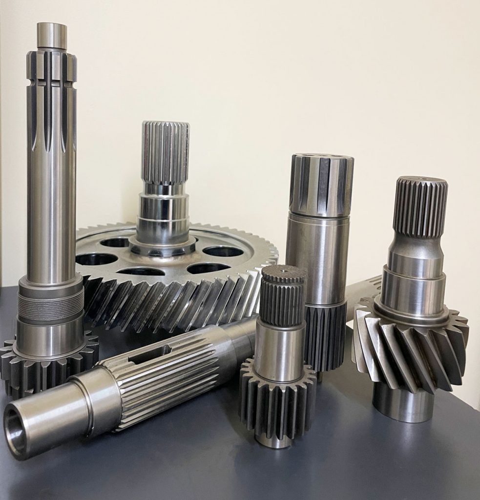
Product Description
Key attributes of Precision Transmission Machinery Parts Rotor Gear Customized Machining Knurling Shaft for Drive
Industry-specific attributes of Precision Transmission Machinery Parts Rotor Gear Customized Machining Knurling Shaft for Drive
| CNC Machining or Not | Cnc Machining |
| Material Capabilities | Aluminum, Brass, Bronze, Copper, Hardened Metals, Precious Metals, Stainless steel, Steel Alloys |
Other attributes of Precision Transmission Machinery Parts Rotor Gear Customized Machining Knurling Shaft for Drive
| Place of Origin | ZheJiang , China |
| Type | Broaching, Drilling, Etching / Chemical Machining, Laser Machining, Milling, Turning, Wire EDM, Other Machining Services |
| Model Number | OEM |
| Brand Name | OEM |
| Material | Metal |
| Process | Cnc Machining+deburrs |
| Surface treatment | Customer’s Request |
| Equipment | CNC Machining Centres / Core moving machine / precision lathe / Automatic loading and unloading equipment |
| Processing Type | Milling / Turning / Stamping |
| OEM/ODM | OEM & ODM CNC Milling Turning Machining Service |
| Drawing Format | 2D/(PDF/CAD)3D(IGES/STEP) |
| Our Service | OEM ODM Customers’drawing |
| Materials Avaliable | Stainless Steel / Aluminum / Metals / Copper / Plastic |
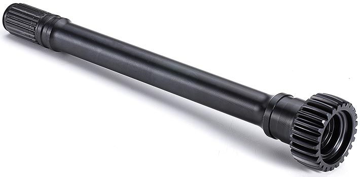
Photo of Customizable Electroplating/Coating/Passivation/Polishing/Sandblasting/Anodize/QPQ Small Batch CNC Machining Part
product inform
ation of Customizable Electroplating/Coating/Passivation/Polishing/Sandblasting/Anodize/QPQ Small Batch CNC Machining Part
| Business Type | Factory / Manufacturer |
| Service | CNC Machining |
| Turning and Milling | |
| CNC Turning | |
| OEM Parts | |
| Material | 1). Aluminum: AL 6061-T6, 6063, 7075-T etc |
| 2). Stainless steel: 303,304,316L, 17-4(SUS630) etc | |
| 3). Steel: 4140, Q235, Q345B,20#,45# etc. | |
| 4). Titanium: TA1,TA2/GR2, TA4/GR5, TC4, TC18 etc | |
| 5). Brass: C36000 (HPb62), C37700 (HPb59), C26800 (H68), C22000(H90) etc | |
| 6). Copper, bronze, Magnesium alloy, Delrin, POM,Acrylic, PC, etc. | |
| Finish | Sandblasting, Anodize color, Blackenning, Zinc/Nickl Plating, Polish, |
| Power coating, Passivation PVD, Titanium Plating, Electrogalvanizing, | |
| Electroplating chromium, electrophoresis, QPQ(Quench-Polish-Quench), | |
| Electro Polishing,Chrome Plating, Knurl, Laser etch Logo, etc. | |
| Main Equipment | CNC Machining center, CNC Lathe, precision lathe |
| Automatic loading and unloading equipment | |
| Core moving machine | |
| Drawing format | STEP,STP,GIS,CAD,PDF,DWG,DXF etc or samples. |
| Tolerance | +/-0.001mm ~ +/-0.05mm |
| Surface roughness | Ra 0.1~3.2 |
| Test Equipment | Complete test lab with Projector, High-low temperature test chamber, Tensile tester Gauge, Salt fog test |
| Inspection | Complete inspection lab with Micrometer, Optical Comparator, Caliper Vernier,CMM |
| Depth Caliper Vernier, Universal Protractor, Clock Gauge | |
| Capacity | CNC turning work range: φ0.5mm-φ150mm*300mm |
| CNC center work range: 510mm*850mm*500mm | |
| Core moving machine work range: φ32mm*85mm | |
| Gerenal Tolerance: (+/-mm) |
CNC Machining: 0.005 |
| Core moving: 0.005 | |
| Turning: 0.005 | |
| Grinding(Flatness/in2): 0.003 | |
| ID/OD Grinding: 0.002 | |
| Wire-Cutting: 0.002 |
RFQ of of Precision Transmission Machinery Parts Rotor Gear Customized Machining Knurling Shaft for Drive /* March 10, 2571 17:59:20 */!function(){function s(e,r){var a,o={};try{e&&e.split(“,”).forEach(function(e,t){e&&(a=e.match(/(.*?):(.*)$/))&&1
| Certification: | ISO9001 |
|---|---|
| Standard: | DIN, ASTM, GOST, GB, JIS, ANSI, BS |
| Customized: | Customized |
| Customization: |
Available
| Customized Request |
|---|
.shipping-cost-tm .tm-status-off{background: none;padding:0;color: #1470cc}
|
Shipping Cost:
Estimated freight per unit. |
about shipping cost and estimated delivery time. |
|---|
| Payment Method: |
|
|---|---|
|
Initial Payment Full Payment |
| Currency: | US$ |
|---|
| Return&refunds: | You can apply for a refund up to 30 days after receipt of the products. |
|---|
How do gear shafts handle changes in rotational direction and torque distribution?
Gear shafts play a crucial role in handling changes in rotational direction and torque distribution in machinery and mechanical systems. Let’s explore how gear shafts accomplish these tasks:
- Rotational Direction Changes:
Gear shafts are designed with gears that have different tooth profiles, sizes, and configurations. By meshing gears with varying characteristics, gear shafts can transmit rotational motion and change the direction of rotation. For example, when a gear with clockwise rotation meshes with a gear with counterclockwise rotation, the gear shaft can transfer the rotational motion and change the direction of output rotation accordingly.
- Torque Distribution:
Gear shafts are also responsible for distributing torque within a mechanical system. Torque is the rotational force applied to the gear shaft, and it needs to be transmitted and distributed to other components or gears in the system. Gear shafts achieve torque distribution through the engagement of multiple gears along the shaft. As torque is applied to the input gear, it transfers through the gear teeth and along the gear shaft, evenly distributing the torque to the output gears. The size, number of teeth, and gear ratios of the gears on the shaft determine the torque distribution characteristics.
- Gear Ratios:
Gear shafts can handle changes in torque distribution by utilizing different gear ratios. The gear ratio is the ratio of the number of teeth between two meshing gears. By using gears with different numbers of teeth, gear shafts can alter the torque distribution between the input and output gears. For example, gearing systems with larger input gears and smaller output gears can amplify torque, while systems with smaller input gears and larger output gears can reduce torque while increasing speed.
- Compound Gear Systems:
In more complex systems, gear shafts may incorporate compound gear arrangements to handle changes in both rotational direction and torque distribution. Compound gears consist of multiple gears mounted on the same shaft, allowing for a combination of gear ratios and rotational direction changes. These arrangements enable gear shafts to accommodate intricate mechanical systems with varying torque and rotational requirements.
Overall, gear shafts handle changes in rotational direction and torque distribution by utilizing different gear configurations, gear ratios, and compound gear systems. Their ability to transmit and distribute rotational motion and torque makes them essential components in machinery and mechanical systems.
Can gear shafts be used in high-torque and heavy-duty applications?
Yes, gear shafts are commonly used in high-torque and heavy-duty applications. Gear systems, including gear shafts, are designed to transmit power and torque between rotating components efficiently. Let’s explore why gear shafts are suitable for such demanding applications:
- Torque Transmission:
Gear shafts are specifically designed to transmit torque effectively. They are capable of handling high levels of torque due to their robust construction and the nature of gear engagement. The teeth of the gears mesh together, allowing the torque to be transferred from one gear to another through the gear shaft. This enables gear shafts to withstand and transmit substantial amounts of torque, making them suitable for high-torque applications.
- Load Distribution:
In heavy-duty applications, where significant loads are involved, gear shafts play a crucial role in distributing the load across multiple gears. By evenly distributing the load, gear shafts prevent excessive stress on individual gears and their associated components. This helps to minimize the risk of gear tooth failure, deformation, or other forms of damage. The load distribution capability of gear shafts contributes to their suitability for heavy-duty applications.
- Sturdy Construction:
Gear shafts are typically constructed using materials known for their strength and durability. High-quality steels or specialized alloys are commonly used to ensure the gear shafts can withstand the demanding conditions of high-torque and heavy-duty applications. The sturdy construction of gear shafts allows them to resist bending, torsion, and other forces that occur under heavy loads, ensuring reliable performance and longevity.
- Supporting Gear Components:
Gear shafts are an integral part of a gear system, working in conjunction with other gear components such as gears, bearings, and housings. These supporting components are designed to handle high loads and provide stability to the gear system as a whole. The combination of well-designed gear shafts and supporting components enhances the overall strength and reliability of the system, making it suitable for high-torque and heavy-duty applications.
- Customization and Engineering:
In situations where standard gear shafts may not meet the specific requirements of a high-torque or heavy-duty application, custom gear shafts can be designed and engineered. Customization allows for the optimization of gear shaft dimensions, materials, and other parameters to meet the unique demands of the application. This ensures that gear shafts are tailored to handle the specific torque and loads encountered in high-torque and heavy-duty applications.
In summary, gear shafts can indeed be used in high-torque and heavy-duty applications. Their ability to transmit torque effectively, distribute loads, sturdy construction, compatibility with supporting gear components, and the potential for customization make them well-suited for such demanding applications. Gear shafts play a crucial role in ensuring reliable and efficient power transmission in high-torque and heavy-duty systems.
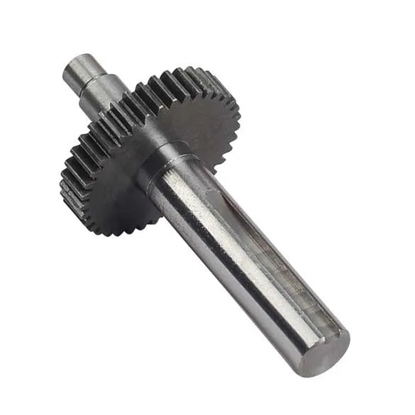
Can you describe the design and construction of a gear shaft?
The design and construction of a gear shaft are crucial factors in ensuring its functionality and durability within a mechanical system. A gear shaft is typically designed and constructed with specific considerations to meet the requirements of the application. Here’s a detailed description of the design and construction aspects of a gear shaft:
- Material Selection:
The choice of material for a gear shaft depends on various factors such as the application, operating conditions, and required strength. Common materials used for gear shafts include steel alloys, such as carbon steel, alloy steel, or stainless steel. These materials offer excellent strength, durability, and resistance to wear and fatigue. In some cases, gear shafts may also be made from other materials like brass or bronze for specific applications.
- Shape and Dimensions:
The shape and dimensions of a gear shaft are determined based on the specific requirements of the gear system and the mechanical system as a whole. Gear shafts are typically cylindrical in shape, with accurate dimensions and tolerances to ensure proper fit and alignment with the gears. The length and diameter of the gear shaft are determined based on factors such as the torque to be transmitted, the space available, and the required stiffness.
- Teeth and Splines:
In gear systems, gear shafts may have teeth or splines to provide a positive engagement with the gears. The teeth or splines are machined onto the gear shaft to ensure accurate meshing and transfer of rotational motion and torque. The shape, size, and profile of the teeth or splines depend on the specific gear system requirements, such as the module or pitch of the gears and the desired gear ratio.
- Bearing Surfaces:
Gear shafts often incorporate bearing surfaces to support and guide the rotation of the shaft within the mechanical system. These bearing surfaces can be in the form of journals or bushings, which reduce friction and wear. The design and construction of these bearing surfaces are critical to minimizing rotational resistance, ensuring smooth operation, and extending the lifespan of the gear shaft.
- Heat Treatment and Surface Finish:
To enhance the strength and durability of a gear shaft, heat treatment processes like quenching and tempering may be applied to improve the material’s properties. These processes can increase the hardness, toughness, and resistance to wear of the gear shaft. Additionally, the surface of the gear shaft may undergo finishing processes such as grinding, polishing, or coating to reduce surface roughness, enhance corrosion resistance, and improve overall performance.
- Accurate Machining and Tolerances:
The manufacturing of a gear shaft involves precise machining processes to achieve accurate dimensions and tolerances. CNC machining or other specialized machining techniques are employed to ensure the gear shaft’s proper fit and alignment with the gears and other components in the mechanical system. Tight tolerances are essential to achieve smooth and efficient operation, minimize backlash, and maintain the desired gear meshing characteristics.
In summary, the design and construction of a gear shaft involve material selection, consideration of shape and dimensions, implementation of teeth or splines, incorporation of bearing surfaces, application of heat treatment and surface finish, and accurate machining with tight tolerances. These design and construction aspects are crucial in creating a gear shaft that can efficiently transmit motion and power, withstand the operating conditions, and provide reliable performance within mechanical systems.


editor by CX 2024-01-11