Product Description
CHINAMFG Machinery offers a wide range of high quality Timing Belt Pulleys and Toothed Bars/ Timing Bars. Standard and non-standard pulleys according to drawings are available .
Types of material:
1. AlCuMgPb 6061 6082 Aluminum Timing Pulley
2. C45E 1045 S45C Carbon Steel Timing Pulley
3. GG25 HT250 Cast Iron Timing Pulley
4. SUS303 SUS304 AISI431 Stainless Steel Timing Pulley
5. Other material on demand, such as cooper, bronze and plastic
Types of surface treatment
1. Anodized surface -Aluminum Pulleys
2. Hard anodized surface — Aluminum Pulleys
3. Black Oxidized surface — Steel Pulleys
4. Zinc plated surface — Steel Pulleys
5. Chromate surface — Steel Pulleys; Cast Iron Pulleys
6. Nickel plated surface –Steel Pulleys; Cast Iron Pulleys
Types of teeth profile
| Teeth Profile | Pitch |
| HTD | 3M,5M,8M,14M,20M |
| AT | AT5,AT10,AT20 |
| T | T2.5,T5,T10 |
| MXL | 0.08″(2.032MM) |
| XL | 1/5″(5.08MM) |
| L | 3/8″(9.525MM) |
| H | 1/2″(12.7MM) |
| XH | 7/8″(22.225MM) |
| XXH | 1 1/4″(31.75MM) |
| STS STPD | S2M,S3M,S4.5M,S5M,S8M,S14M |
| RPP | RPP5M,RPP8M,RPP14M,RPP20M |
| PGGT | PGGT 2GT, 3GT and 5GT |
| PCGT | GT8M,GT14M |
Types of pitches and sizes
Imperial Inch Timing Belt Pulley,
1. Pilot Bore MXL571 for 6.35mm timing belt; teeth number from 16 to 72;
2. Pilot Bore XL037 for 9.53mm timing belt; teeth number from 10 to 72;
3. Pilot Bore, Taper Bore L050 for 12.7mm timing belt; teeth number from 10 to 120;
4. Pilot Bore, Taper Bore L075 for 19.05mm timing belt; teeth number from 10 to 120;
5. Pilot Bore, Taper Bore L100 for 25.4mm timing belt; teeth number from 10 to 120;
6. Pilot Bore, Taper Bore H075 for 19.05mm timing belt; teeth number from 14 to 50;
7. Pilot Bore, Taper Bore H100 for 25.4mm timing belt; teeth number from 14 to 156;
8. Pilot Bore, Taper Bore H150 for 38.1mm timing belt; teeth number from 14 to 156;
9. Pilot Bore, Taper Bore H200 for 50.8mm timing belt; teeth number from 14 to 156;
10. Pilot Bore, Taper Bore H300 for 76.2mm timing belt; teeth number from 14 to 156;
11. Taper Bore XH200 for 50.8mm timing belt; teeth number from 18 to 120;
12. Taper Bore XH300 for 76.2mm timing belt; teeth number from 18 to 120;
13. Taper Bore XH400 for 101.6mm timing belt; teeth number from 18 to 120;
Metric Timing Belt Pulley T and AT
1. Pilot Bore T2.5-16 for 6mm timing belt; teeth number from 12 to 60;
2. Pilot Bore T5-21 for 10mm timing belt; teeth number from 10 to 60;
3. Pilot Bore T5-27 for 16mm timing belt; teeth number from 10 to 60;
4. Pilot Bore T5-36 for 25mm timing belt; teeth number from 10 to 60;
5. Pilot Bore T10-31 for 16mm timing belt; teeth number from 12 to 60;
6. Pilot Bore T10-40 for 25mm timing belt; teeth number from 12 to 60;
7. Pilot Bore T10-47 for 32mm timing belt; teeth number from 18 to 60;
8. Pilot Bore T10-66 for 50mm timing belt; teeth number from 18 to 60;
9. Pilot Bore AT5-21 for 10mm timing belt; teeth number from 12 to 60;
10. Pilot Bore AT5-27 for 16mm timing belt; teeth number from 12 to 60;
11. Pilot Bore AT5-36 for 25mm timing belt; teeth number from 12 to 60;
12. Pilot Bore AT10-31 for 16mm timing belt; teeth number from 15 to 60;
13. Pilot Bore AT10-40 for 25mm timing belt; teeth number from 15 to 60;
14. Pilot Bore AT10-47 for 32mm timing belt; teeth number from 18 to 60;
15. Pilot Bore AT10-66 for 50mm timing belt; teeth number from 18 to 60;
Metric Timing Belt Pulley HTD3M, 5M, 8M, 14M
1. HTD3M-06; 3M-09; 3M-15; teeth number from 10 to 72;
2. HTD5M-09; 5M-15; 5M-25; teeth number from 12 to 72;
3. HTD8M-20; 8M-30; 8M-50; 8M-85 teeth number from 22 to 192;
4. HTD14M-40; 14M-55; 14M-85; 14M-115; 14M-170; teeth number from 28-216;
5. Taper Bore HTD5M-15; 8M-20; 8M-30; 8M-50; 8M-85; 14M-40; 14M-55; 14M-85;
14M-115; 14M-170
Metric Timing Belt Pulleys for Poly Chain GT2 Belts
1. PCGT8M-12; PCGT8M-21; PCGT8M-36; PCGT8M-62;
2. PCGT14M-20; PCGT14M-37; PCGT14M-68; PCGT14M-90; PCGT14M-125;
Power Grip CHINAMFG Tooth/ PGGT 2GT, 3GT and 5GT
1. 2GT-06, 2GT-09 for timing belt width 6mm and 9mm
2. 3GT-09, 3GT-15 for timing belt width 9mm and 15mm
3. 5GT-15, 5GT-25 for timing belt width 15mm and 25mm
OMEGA RPP HTD Timing Pulleys
1. RPP3M-06; 3M-09; 3M-15; teeth number from 10 to 72;
2. RPP5M-09; 5M-15; 5M-25; teeth number from 12 to 72;
3. RPP8M-20; 8M-30; 8M-50; 8M-85 teeth number from 22 to 192;
4. RPP14M-40; 14M-55; 14M-85; 14M-115; 14M-170; teeth number from 28-216;
5. Taper Bore RPP5M-15; 8M-20; 8M-30; 8M-50; 8M-85; 14M-40; 14M-55; 14M-85;
14M-115; 14M-170 /* March 10, 2571 17:59:20 */!function(){function s(e,r){var a,o={};try{e&&e.split(“,”).forEach(function(e,t){e&&(a=e.match(/(.*?):(.*)$/))&&1
| Standard Or Nonstandard: | Standard |
|---|---|
| Application: | Motor, Motorcycle, Machinery, Marine, Agricultural Machinery, Industry |
| Hardness: | Soft Tooth Surface |
| Manufacturing Method: | Rolling Gear |
| Toothed Portion Shape: | Spur Gear |
| Material: | Cast Iron |
| Samples: |
US$ 4/Piece
1 Piece(Min.Order) | |
|---|
| Customization: |
Available
| Customized Request |
|---|

What are the safety considerations when working with gear shafts?
Working with gear shafts involves potential hazards that need to be considered to ensure the safety of individuals involved. Proper safety measures should be followed to prevent accidents and injuries. Let’s explore some important safety considerations when working with gear shafts:
- Personal Protective Equipment (PPE):
Wearing appropriate personal protective equipment is essential when working with gear shafts. This may include safety glasses or goggles to protect the eyes from flying debris, gloves to provide hand protection, and appropriate footwear to prevent foot injuries. PPE should be selected based on the specific hazards associated with the task.
- Machine Guarding:
Ensure that gear shafts and related machinery are properly guarded. Machine guards help prevent accidental contact with moving parts and reduce the risk of entanglement or entrapment. Guards should be in place and functioning correctly before any work is performed on or near gear shafts.
- Lockout/Tagout Procedures:
Prior to working on gear shafts, it is important to follow lockout/tagout procedures. These procedures involve isolating the machinery from its power source and ensuring that it cannot be energized accidentally. Lockout/tagout procedures help protect workers from unexpected startup or release of stored energy, minimizing the risk of injury.
- Proper Training and Knowledge:
Workers should receive proper training on the safe operation and maintenance of gear shafts. They should be familiar with the potential hazards, safety procedures, and emergency protocols. Training should cover topics such as safe handling, proper use of tools, and awareness of potential risks associated with gear shafts.
- Risk Assessment:
Conduct a thorough risk assessment before performing any work involving gear shafts. Identify potential hazards, assess the associated risks, and implement appropriate control measures. This may include evaluating the stability of the work area, assessing the need for additional support or lifting equipment, and identifying any potential pinch points or crush hazards.
- Proper Lifting Techniques:
When handling or moving gear shafts, use proper lifting techniques to prevent strain or injury. Avoid lifting heavy loads manually when possible and use mechanical lifting aids or equipment when necessary. Ensure that lifting equipment is in good working condition, properly rated for the load, and operated by trained personnel.
- Clean and Organized Work Area:
Maintain a clean and organized work area around gear shafts. Remove any unnecessary items or debris that could pose a tripping or slipping hazard. Keep tools and equipment properly stored when not in use to prevent accidents and injuries.
- Regular Maintenance and Inspection:
Perform regular maintenance and inspection of gear shafts to ensure their safe operation. Check for signs of wear, damage, or misalignment. Address any issues promptly and follow manufacturer’s guidelines for maintenance intervals and procedures. Regular inspections help identify potential safety concerns and prevent equipment failure.
- Communication and Collaboration:
Encourage effective communication and collaboration among team members when working with gear shafts. Clear communication ensures that everyone is aware of their roles and responsibilities and can alert others to potential hazards or unsafe conditions. Collaboration promotes a safety culture and allows for the sharing of knowledge and best practices.
By considering these safety measures when working with gear shafts, the risk of accidents and injuries can be significantly reduced. It is important to prioritize safety and create a work environment where individuals are informed, trained, and equipped to work safely with gear shafts.

How do you select the appropriate material for constructing a gear shaft?
Selecting the appropriate material for constructing a gear shaft is crucial for ensuring its durability, strength, and overall performance within a mechanical system. Several factors need to be considered when choosing the material for a gear shaft. Let’s explore the process of selecting the appropriate material:
- Load and Torque Requirements:
The first step in material selection is assessing the load and torque requirements of the gear shaft. Consider the maximum load the gear shaft will experience during operation, as well as the torque it needs to transmit. These factors determine the material’s strength and fatigue resistance needed to withstand the applied forces without deformation or failure.
- Wear Resistance:
Gears undergo constant contact and sliding motion, which can lead to wear over time. Therefore, it is important to consider the wear resistance of the material for the gear shaft. Materials with high hardness, such as hardened steels or specific alloys, are often preferred due to their ability to resist wear and withstand the repetitive contact between gear teeth.
- Fatigue Resistance:
Gear shafts are subjected to cyclic loading, which can cause fatigue failure if the material is not able to withstand these repeated stress cycles. It is essential to choose a material with good fatigue resistance to ensure that the gear shaft can withstand the expected number of load cycles without premature failure. Steels with appropriate alloying elements or specialized alloys like nickel-chromium-molybdenum alloys are commonly used for their high fatigue resistance.
- Torsional Strength:
Torsional strength refers to a material’s ability to resist twisting or torsional forces. Gear shafts transmit torque, and therefore, the selected material should have sufficient torsional strength to handle the applied torque without excessive deformation or failure. Steels, particularly those with high carbon content, are often chosen for their excellent torsional strength.
- Heat Treatment Capability:
The ability to heat treat the material is an important consideration in gear shaft selection. Heat treatment processes like quenching and tempering can significantly enhance the mechanical properties of certain materials, such as steels. Heat treatment can improve hardness, strength, and toughness, allowing the gear shaft to withstand higher loads and provide better performance.
- Corrosion Resistance:
In applications where the gear shaft may be exposed to corrosive environments, selecting a material with good corrosion resistance is essential. Stainless steels or corrosion-resistant alloys like bronze or brass are often used to prevent degradation due to moisture, chemicals, or other corrosive agents.
- Manufacturability and Cost:
Considerations of manufacturability and cost are also important in material selection. The chosen material should be readily available, easily machinable, and cost-effective for the specific application. Balancing the desired material properties with manufacturing feasibility and cost constraints is crucial to achieve an optimal solution.
In summary, selecting the appropriate material for constructing a gear shaft involves considering factors such as load and torque requirements, wear resistance, fatigue resistance, torsional strength, heat treatment capability, corrosion resistance, manufacturability, and cost. Evaluating these factors enables the identification of a material that can provide the necessary strength, durability, and overall performance for the gear shaft within the specific mechanical system.

Can you describe the design and construction of a gear shaft?
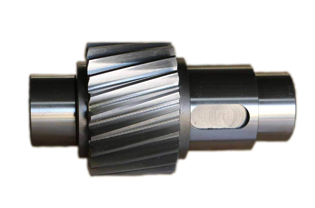
The design and construction of a gear shaft are crucial factors in ensuring its functionality and durability within a mechanical system. A gear shaft is typically designed and constructed with specific considerations to meet the requirements of the application. Here’s a detailed description of the design and construction aspects of a gear shaft:
- Material Selection:
The choice of material for a gear shaft depends on various factors such as the application, operating conditions, and required strength. Common materials used for gear shafts include steel alloys, such as carbon steel, alloy steel, or stainless steel. These materials offer excellent strength, durability, and resistance to wear and fatigue. In some cases, gear shafts may also be made from other materials like brass or bronze for specific applications.
- Shape and Dimensions:
The shape and dimensions of a gear shaft are determined based on the specific requirements of the gear system and the mechanical system as a whole. Gear shafts are typically cylindrical in shape, with accurate dimensions and tolerances to ensure proper fit and alignment with the gears. The length and diameter of the gear shaft are determined based on factors such as the torque to be transmitted, the space available, and the required stiffness.
- Teeth and Splines:
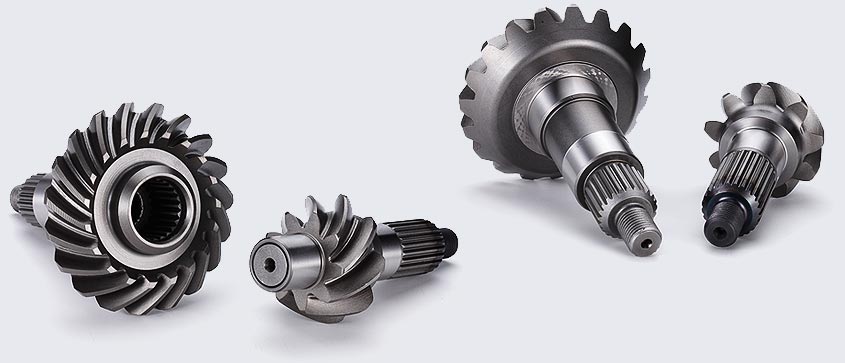
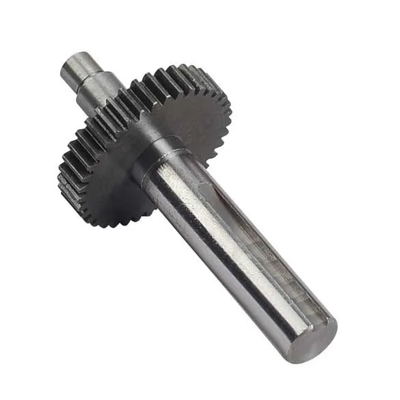
In gear systems, gear shafts may have teeth or splines to provide a positive engagement with the gears. The teeth or splines are machined onto the gear shaft to ensure accurate meshing and transfer of rotational motion and torque. The shape, size, and profile of the teeth or splines depend on the specific gear system requirements, such as the module or pitch of the gears and the desired gear ratio.
- Bearing Surfaces:
Gear shafts often incorporate bearing surfaces to support and guide the rotation of the shaft within the mechanical system. These bearing surfaces can be in the form of journals or bushings, which reduce friction and wear. The design and construction of these bearing surfaces are critical to minimizing rotational resistance, ensuring smooth operation, and extending the lifespan of the gear shaft.
- Heat Treatment and Surface Finish:
To enhance the strength and durability of a gear shaft, heat treatment processes like quenching and tempering may be applied to improve the material’s properties. These processes can increase the hardness, toughness, and resistance to wear of the gear shaft. Additionally, the surface of the gear shaft may undergo finishing processes such as grinding, polishing, or coating to reduce surface roughness, enhance corrosion resistance, and improve overall performance.
- Accurate Machining and Tolerances:
The manufacturing of a gear shaft involves precise machining processes to achieve accurate dimensions and tolerances. CNC machining or other specialized machining techniques are employed to ensure the gear shaft’s proper fit and alignment with the gears and other components in the mechanical system. Tight tolerances are essential to achieve smooth and efficient operation, minimize backlash, and maintain the desired gear meshing characteristics.
In summary, the design and construction of a gear shaft involve material selection, consideration of shape and dimensions, implementation of teeth or splines, incorporation of bearing surfaces, application of heat treatment and surface finish, and accurate machining with tight tolerances. These design and construction aspects are crucial in creating a gear shaft that can efficiently transmit motion and power, withstand the operating conditions, and provide reliable performance within mechanical systems.


editor by CX 2024-01-11